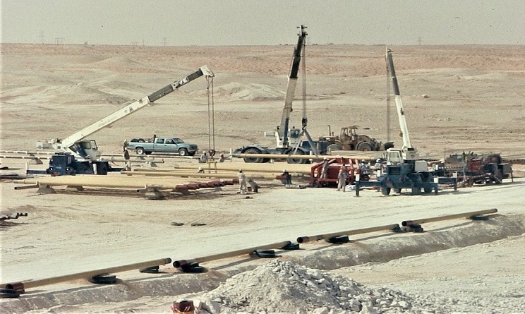
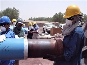
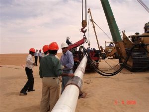
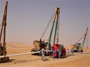
TYPICAL FIRST END YARD INSTALLATION
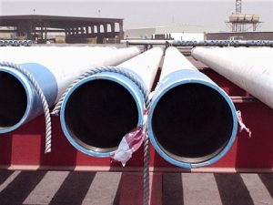
(PIPES BEING FED BY CRANE)
TYPICAL
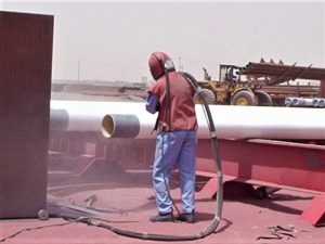
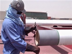
1. Blast cleanPipe-ends OD (SA 2 ½ surface preparation – SSPC SP 10) for rust and mil scalecleaning to the required insert depth. For externally FBE coated pipes, the OD cutback lengh is blast-cleaned to SA 2 ½ surface preparation for about the coupling insertion depth, which is the length of coupling divided by 2 minus 3/8 -inch.
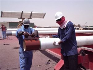 3. When the lined-up pipessatis factorily met the pipe end conformance requirements, the required insertion depth is marked on the external surface of the pipe end. Just before first-end PSC pipe insertion, a lubricant/sealant is applied to about ¾ of the insertion depth on the external surface of pipe end and on the pipe end bevel.
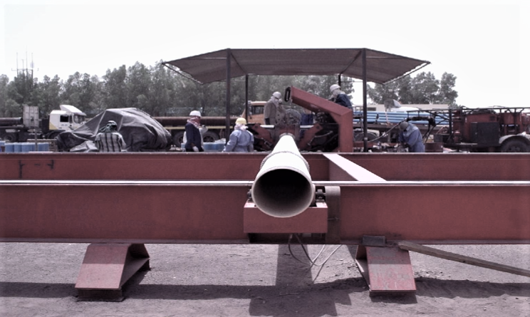
 5. Pipe ready for first end insertion is rolled on the pipe rack lined–up to the PSC joining equipment pipe door. The lubricant/sealant is applied to about ¾ of the insertion depth on the external surface of pipe end and on the pipe end bevel.With the use of a crane or feed roller, the pipe will be brought into the PSC joining unit.
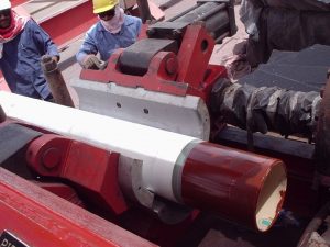
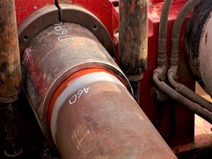
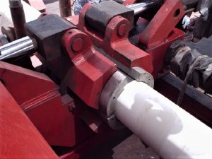 7. The pipe doors are hydraulically closed around the pipe and the smooth aluminum pipe slips grip onto externally coated pipe without damaging the coating.
 9. After the first PSC pipe end insertion, the pipe/PSC combination is rolled longitudinally out of the FJU back onto the pipe racks. It is then rolled laterally to the lubricant/sealant residue cleaning station.
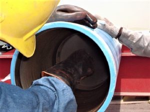 11. Lubricant/sealant residue is then cleaned from the exposed face of the SRG and the PSC center interior surface.
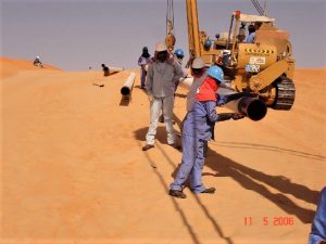
TYPICAL FIRST END YARD INSTALLATION
(PIPES BEING FED BY ROLLERS)
TYPICAL
2. Pre-inspection of pipe ends conformance follows to include grinding-off pipe-end bevel’s sharp edge, Go - No Go ring verification and pipe wall thickness gauge verification with the aide of UT wall thickness gauge.
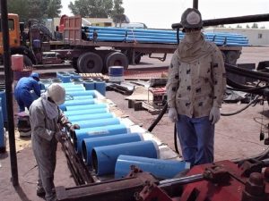
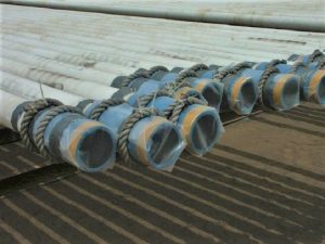
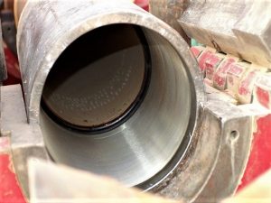
4. On the coupling side flank of the Field-joining unit, Positive Seal Couplings internal surface are inspected. Power brush cleaning using a circular wire brush ONLY (with fine wire strands) is the approved method for cleaning PSC internal if required. An SRG (Spacer Ring Gasket) is inserted and placed upright at the middle recess area of the coupling (halfway). Lubricant/sealant is also applied to the coupling lined-up to be fed on the coupling bowl of the FJU. (Lubricant/sealant is applied to a depth-half the length of the coupling)
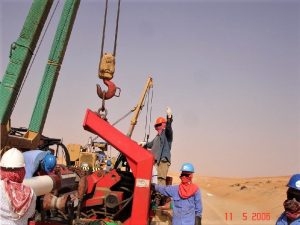
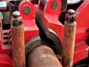
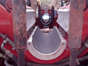 6. On the opposite end of the PSC joining unit (background of the photo), a coupling will be fed into the coupling door manually for lightweight couplings and by the use of an electric hoist when practical. In the foreground of the photo are the open pipe door “slips” (aluminum) with a friction grip pad in the lower bowl. These pipe door slips will be closed around the pipe to firmly grip the pipe for insertion into a PSC.
 8. The coupling doors are hydraulically closed around the PSC and the steel coupling slips hold on the PSC firmly in position for pipe end insertion. After the pipe end and PSC are aligned, the pipe is then inserted into the PSC by the horizontal travel of the JU retracting hydraulic “ram” cylinders. All hydraulic functions are controlled by the JU operator with directional control valves.
 10. Using a special seating tool, the SRG is then seated firmly against the first pipe end bevel face in the center of the PSC.
 12. Before loading the pipe with Positive Seal Pipe Coupling on trucks for transport, the pipe should be blown out with compressed air to remove all dirt, sand or other foreign matter. The pipe-ends and PSC ends will then be wrapped with plastic and taped in such a way to ensure the internal areas of the pipe and coupling remain free of dirt, sand and other foreign matter. If the PSC’s were provided with plastic end plugs, re-install the end plugs back into the PSCs before shipping out.
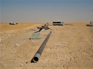 1. Couplings are often installed on one end of each joint (first end PSC) before the pipe is brought to the field. The pipes with first end PSCs previously installed are strung along the ROW with the PSC end of each pipe oriented in the direction of the pipe lay.
 3. Prior to positioning the PSC machine at each pipeline start point,a sufficient quantity of pipe ends OD external surface insertion depth must already be blast cleaned and completed the FAFPC pipe ends conformance verification. The insertion depth is blast-cleaned to SA2 ½ surface preparation.
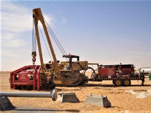 5. The hook of a pipelayer sideboom (Caterpillar 594 or equivalent) is attached to the Joining Unit (JU) lifting master link at the kickoff point of the pipeline and this sideboom lifts and suspends the JU for pipeline construction. The capacity of the required sideboom shall be specified by Jetair Int’l for the JU model to be used.
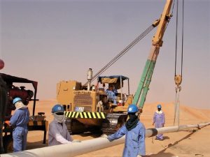 7. From behind the JU, a “catchoff’’ sideboom(s) lifts and supports the pipeline weight off of the JU and, at the direction of the JU operator, helps align the pipeline with the JU. The catch-off sideboom(s) also lays the pipeline into the ditch or onto pipeline supports, again at the direction of the JU operator, and then moves ahead nearer the JU to again lift and support the pipeline weight.
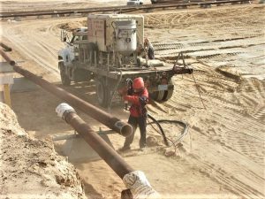
 9. A specially formulated lubricant/sealant is applied (about 2/3 of insertion depth) to the exterior surface of the pipe end, and over the full insertion depth of interior of the mechanical connector. The set-in sideboom cautiously brings the pipe end closer to the coupling, guided by the pipe lift vee roller on the FJU and spotted by the FJU operator.
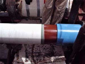
 11. The JU operator inserts the pipe end into the coupling until the correct insertion depth is achieved. The pipe-joining unit maintains correct alignment during insertion while the hydraulic rams exert the amount of axial force needed to insure the full insertion depth and pipe ends seated (with the SRG energized in between the pipe ends - conformed to the standard API bevel) completing a strong and lasting bond.
 13. The raised kicker rollers are cautiously lowered down by the JU operator as the pipe end with attached coupling approaches to theJU’s stationary block and alert the cradle sideboom operator on a full stop when the coupling attached to the pipe end is caught on the shoulder of the JU’s coupling door slip. The JU operator then grips the coupling door around the coupling slip, ready for the next pipe joint to coupling connection.
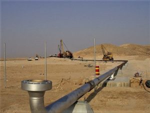 15. These steps shall be done repeatedly until the pipeline or sections of pipeline are installed. The PSC pipeline is lowered directly in place by the catch-off sideboom. However, coordinated Jetair / prime contractor planning must be done for tie-ins to elbows, tees, road/pipeline crossings, pipeline ends etc. A follow-up crew can complete any external coating if required.
 2. The center of equilibrium for each pipe shall be determined and marked for the rigger to easily place the lifting slings or quick release pipe tong.
 4. The second end of the coupling for the second end insertion pipe lay shall also be visually inspected for rust, dirt, sand, or any foreign matter. Rust and adhering contaminants shall be removed with a straight die power grinder tool using a circular wire brush ONLY. Only if power is not available, then hand wire brushes are allowed. Take necessary precaution to keep the rotating wire brush away from the SRG and pipe’s internal coating.
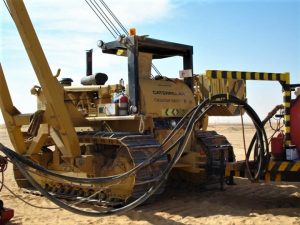 6. The JU’s hydraulic power unit (HPU), which is mounted on its own two-wheeled trailer is hooked to the back of the sideboob suspending the JU using the HPU trailer’s pintle eye and the side booms rear pintle pin.
 8. Ahead of the JU, a “set-in” pipelayer sideboom picks up the next pipe to be installed and sets it into the JU’s pipe slips with the bare, blast cleaned end oriented towards the pipeline end PSC in the JU. Before commencing with the installation (pipe end insertion), the correct insert depth shall be measured and marked on the OD of
line pipe end.
 10. The pipe door slips grip around the pipe and the coupling slips hold the PSC in position. After the pipe and PSC are aligned, the JU operator retracts the horizontal hydraulic “ram” cylinders to insert the pipe end into the second PSC end. All JU hydraulic functions are controlled by the JU operator by use of directional control valves on the JU’s control panel.
 12. Upon the instruction of the JU operator, the set-in side-boom releases the joint and move forward to pick-up the next pipe joint for connection. The JU operator then opens the pipe and coupling doors, raises the kicker rollers to release its grip on the connected pipe joint, and then instructed the operator of the cradle side-boom to traverse the ROW (as the cradle side-boom carries the JU to the subsequent coupling) while the pipe slides along the raised kicker roller.